Views: 0 Author: Site Editor Publish Time: 2026-09-25 Origin: Site
Poor power transmission will quickly ruin a machine's lifespan. Selecting the wrong gearbox causes costly end-user downtime, which directly damages your reputation as an equipment manufacturer. The actual field performance and longevity of an Original Equipment Manufacturer machine depend entirely on the structural integrity of its internal drive components.
To build better machinery, engineering teams need to look past basic marketing catalogs. They must understand the nuanced mechanics of their drive systems. We designed this technical guide specifically for equipment builders. You will learn practical selection strategies to specify the right mechanical drive for your unique architecture, ensuring seamless integration and maximizing operational uptime.
Understand the Load: Properly matching nominal torque, backlash tolerances, and gear ratio requirements is the foundation of reliable machine architecture.
Match Type to Application: High-dynamic robotics demand precision units. Meanwhile, heavy industrial applications require specialized hardened series to survive extreme shock loads.
Leverage Modular Designs: Standardized base units offer space-saving versatility and simplify supply chain management for high-torque requirements.
Calculate Total Cost: Sourcing is never just about the initial unit price. Maintenance intervals, lifetime lubrication, and factory engineering support heavily dictate the Total Cost of Ownership.
Competitive machinery requires robust power transmission. A planetary gear reducer is a highly efficient mechanical device. It consists of a central sun gear, multiple planet gears mounted on a carrier, and an outer ring gear. As the servo motor drives the sun gear, the planet gears revolve around it. This transfers immense power to the output shaft.
This kinematic arrangement offers massive advantages over traditional parallel shaft or worm gearboxes. The mechanical load distributes simultaneously across multiple planet gears. Because of this shared-load mechanics, these reducers transmit significantly higher torque levels within a much smaller physical footprint. It prevents single-point tooth stress and enhances overall durability.
Modern automated guided vehicles and complex packaging lines require strict space optimization. The coaxial design allows the motor and output shaft to align perfectly. This saves critical installation space and reduces the overall weight of the machine build. Furthermore, field data shows these gearboxes operate at 95% to 98% efficiency per stage. This minimal energy loss translates to lower electricity consumption and drastically reduces thermal output.
Macroeconomic trends are rapidly reshaping power transmission design. The acceleration of smart manufacturing forces equipment builders to rethink their drivetrain layouts. End-users now demand smaller, faster, and smarter machines. This drive toward miniaturization means engineers can no longer rely on bulky gear motors. Instead, they require extreme torque density packed into highly compact envelopes.
Predictive maintenance is also becoming a standard expectation. Modern builders increasingly pair their gearboxes with IoT-enabled vibration and temperature sensors. By monitoring the micro-vibrations of the gear meshing in real-time, maintenance teams can predict bearing fatigue before catastrophic failure occurs. Selecting a gearbox with a housing designed to accommodate these diagnostic sensors provides a massive competitive edge for your sales team.
Procurement managers and mechanical engineers must thoroughly evaluate critical technical parameters. Skipping this step leads directly to premature mechanical failure.
Specification | Technical Definition | Application Impact |
|---|---|---|
Nominal & Peak Torque | The continuous torque measured in Newton meters the gearbox handles versus the maximum shock load it survives. | Ensures the machine operates continuously without gear shearing during emergency halts. |
Gear Ratio | The mathematical ratio of input speed to output speed, such as a 10 to 1 ratio. | Dictates final operating speed and torque multiplication. Must perfectly match the servo profile. |
Backlash | The clearance between mating gear teeth, measured in arcminutes. | Directly impacts positioning accuracy. High backlash causes jitter; low backlash ensures precise cutting. |
Radial & Axial Loads | Radial forces act perpendicular to the shaft; axial forces act parallel. | Exceeding limits destroys internal bearings. Proper calculation dictates required bearing size. |
Choosing between standard industrial tolerance and high-precision tolerance is a major turning point in the design phase. Over-specifying increases costs unnecessarily. Under-specifying leads to wildly inaccurate machine performance.
Standard units are manufactured with conventional machining tolerances. They typically exhibit a backlash of 8 to 15 arcminutes. These units are highly durable and cost-effective. They are ideal for applications where continuous rotation is the primary goal, like conveyor belts and industrial mixers where pinpoint stopping accuracy is not required.
In contrast, a precision planetary gear reducer is engineered with ground gears and extremely tight manufacturing tolerances. These units deliver ultra-low backlash, often under 3 arcminutes. They provide exceptional torsional stiffness and smooth, vibration-free operation. They are unequivocally mandatory for high-dynamic applications. Builders utilize these in 6-axis robotics, CNC machining centers, and precision medical imaging equipment. If the machine must return to an exact coordinate repeatedly without micro-deviations, you need a precision unit.
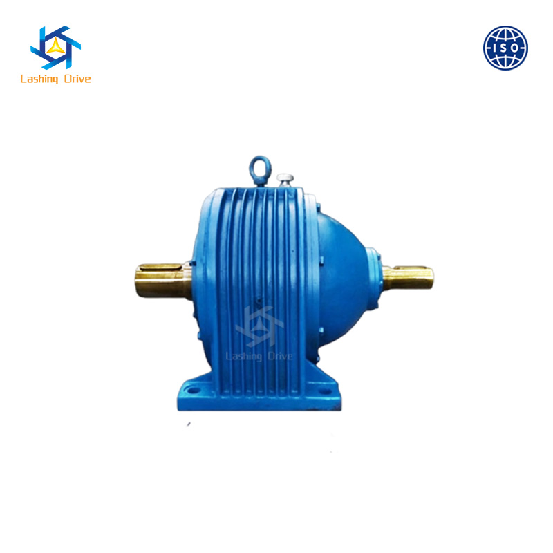
Standard commercial gearboxes fail quickly when deployed into harsh, high-load environments. The NGW series planetary gear reducer is specifically designed to meet the unforgiving demands of heavy industrial sectors.
This series represents a class of hardened tooth surface speed reducers. They feature involute cylindrical gears that are carburized and quenched. This metallurgical treatment hardens the gear surface for extreme wear resistance while maintaining a tough, shock-absorbing inner core. This specific geometry ensures smooth meshing, significantly reducing operational noise and minimizing friction-induced wear under extreme loads.
Engineers select this series for its proven durability in highly abrasive and high-vibration environments. It is the industry standard for metallurgy equipment, mining operations, heavy lifting cranes, and cement manufacturing plants. Its resistance to tooth wear under continuous, heavy-duty cycles lowers warranty claims drastically.
Flexibility in design and assembly is a major competitive advantage for modern industrial machinery. The P series planetary gear reducer addresses this need by offering a standardized, modular approach to high-torque power transmission.
Instead of casting unique housings for every specific application, this heavy-duty gearbox uses standardized base units. Engineers can configure these with various input and output modules. You can specify multiple output configurations from the very same base unit. Options include solid shafts with keyways, involute splined hollow shafts, and hollow shafts with shrink discs for keyless, zero-backlash connections.
The primary driver for selecting this modular series is supply chain versatility. A manufacturer can purchase a single base series and adapt it across multiple different machine models simply by changing the mounting flanges. This standardization simplifies inventory management, reduces lead times, and streamlines complex engineering designs. It is heavily utilized in the wind power sector and heavy construction machinery.
Selecting the appropriate power transmission component requires a methodical approach. Miscalculations in the sizing phase inevitably lead to excessive vibration or inadequate power delivery. Establishing a standardized selection protocol is vital.
The first critical step is evaluating the duty cycle. Duty cycles dictate the thermal and mechanical stress placed on internal components. In continuous duty applications, the motor and gearbox run at a constant load long enough to reach thermal equilibrium. Here, you must prioritize thermal capacity. Intermittent duty involves frequent starts, stops, and directional changes. This introduces high dynamic loads, making peak acceleration torque the primary selection criterion.
Next, calculate the service factor. Nominal torque ratings assume an ideal, uniform load operating for a standard eight-hour shift. Real-world industrial environments rarely offer ideal conditions. The service factor is a safety multiplier. A light conveyor might use a service factor of 1.0 to 1.25. However, a rock crusher running around the clock with heavy shock loads requires a service factor of 1.75 to 2.0 or higher to prevent gear shearing.
Mechanical compatibility between the motor and the gearbox is non-negotiable. The input flange must perfectly align with the dimensions of the selected servo or AC motor. You must also calculate the inertia matching ratio. The inertia of the load reflected back to the motor must be kept within an acceptable range, typically a 5 to 1 ratio for highly dynamic servos, to ensure precise stability without motor oscillation.
A gearbox supplier is a strategic engineering partner. The quality of support they provide directly influences your time-to-market. A reputable manufacturer should provide robust pre-sales engineering support, including immediate access to accurate 3D CAD models in STEP or IGES formats for seamless digital assembly.
While off-the-shelf units satisfy many requirements, bespoke machinery often demands customized solutions. Assess whether the manufacturer can modify standard units without imposing exorbitant minimum order quantities. Common requests include custom output shaft dimensions or specialized anti-corrosion surface treatments. Always audit the supplier's quality assurance protocols to ensure they conduct rigorous noise, vibration, and leak testing before shipment.
Purchasing departments are frequently pressured to minimize initial capital expenditure. However, evaluating a drivetrain solely on its unit price is a fundamentally flawed strategy. Cheaper units often utilize inferior bearing materials, lower-grade steel, or less precise machining tolerances.
These compromises manifest as increased internal friction, higher operating temperatures, and accelerated wear. The equipment builder then faces increased warranty claims. Maintenance requirements also significantly influence the total cost. Premium units feature lifetime lubrication, meaning they are factory-sealed with high-grade synthetic oil and require no fluid changes for up to 30,000 hours. Cheaper alternatives require regular oil draining, adding continuous labor costs.
When a low-quality gearbox fails, the end-user's production line stops. Unplanned downtime costs facilities tens of thousands of dollars per hour. Providing a machine engineered with highly reliable components minimizes this risk and serves as a powerful selling point.
Selecting the correct gear reducer ensures optimal machine performance, precise load handling, and long-term mechanical reliability. Always match your torque, inertia, and environmental requirements carefully during the initial design phase to avoid costly retrofits later in the production cycle.
By understanding the distinct advantages of precision units, heavy-duty hardened series, and modular architectures, equipment builders can tailor their drivetrains to outpace the competition. Prioritize the Total Cost of Ownership over the initial unit price to guarantee your final machinery performs flawlessly in the field. Ready to upgrade your machine's drivetrain? Explore high-performance solutions and technical specifications at CN Lashing to find the exact mechanical drive tailored to your architectural needs.
A precision unit is manufactured with exceptionally tight machining tolerances, resulting in extremely low backlash, often under 3 arcminutes. This high level of torsional stiffness makes it ideal for highly dynamic applications like robotics and CNC machining. Standard reducers are designed with slightly higher tolerances for backlash, usually 8 to 15 arcminutes, and are utilized for general power transmission tasks where absolute positional accuracy is not required.
This series features heavily hardened gear teeth and a highly durable involute cylindrical gear design. It is engineered specifically to withstand massive load-bearing requirements and harsh shock loads. Builders frequently integrate this series into heavy-duty industrial applications such as mining equipment, metallurgical machinery, cement manufacturing plants, and heavy lifting hoists.
This specific series is distinguished by its standardized and modular design architecture. This modularity allows for a vast array of input and output configurations, including solid shafts, hollow shafts, and shrink disc connections, all from a single base unit. This versatility simplifies inventory management and overall engineering complexity across multiple machine models.
The operational lifespan depends heavily on proper initial sizing, adherence to correct service factors, and the operating environment. When accurately matched to the application's duty cycle with appropriate lubrication, a high-quality drive can last anywhere from 20,000 to 30,000 operating hours. In continuous applications, this translates to several years of uninterrupted service.
Yes, unlike certain worm gear designs which can be mechanically self-locking due to high friction angles, these concentric gearboxes can generally be back-driven. Because they are highly efficient, external forces applied to the output shaft can transmit power backward through the gear train to rotate the motor. If an application requires holding a heavy load in place when the motor is powered off, a separate mechanical holding brake must be integrated into the system.
To determine the correct gear ratio, you must divide the servo motor's rated input speed by your application's required output speed. Additionally, you must ensure the ratio provides enough torque multiplication to handle the load while keeping the inertia matching ratio between the load and the motor within a stable range, typically under a 10 to 1 ratio.
Overheating is usually caused by selecting a unit with insufficient thermal capacity for continuous duty cycles, using the wrong viscosity of lubrication, or exceeding the maximum input speed. To prevent this, correctly identify your duty cycle during the sizing phase, ensure the service factor accounts for ambient temperatures, and strictly follow the manufacturer's synthetic lubrication guidelines.