Views: 0 Author: Site Editor Publish Time: 2026-09-18 Origin: Site
Heavy industrial loads crush standard gearboxes daily. When engineering systems for massive force multiplication, a conventional setup often reaches its mechanical limits far too quickly under immense stress. Undersized drives yield catastrophic mechanical failures. These failures halt production lines and drain repair budgets. Conversely, oversized units waste valuable project capital and consume unnecessary spatial real estate.
The ultimate solution lies in selecting a highly engineered high torque planetary gear reducer. Designed specifically to manage massive rotational forces within a compact footprint, these units fundamentally change how mechanical power is transmitted. This comprehensive guide breaks down the rigorous engineering process of sizing these powerful units. We will ensure your next heavy-duty project achieves maximum reliability and efficiency.
High Torque Density: Planetary systems offer superior torque-to-weight ratios because the mechanical load is shared among multiple planet gears simultaneously.
Accurate Sizing is Crucial: Proper specification goes beyond baseline power. It requires calculating nominal torque, peak shock loads, radial and axial forces, and applying the correct service factor.
Application-Specific Solutions: Heavy-duty variants are specifically engineered with robust housings and premium metallurgy for severe industrial environments.
Versatile Integration: Integrating fluid power with planetary gearing provides exceptional low-speed, high-torque control for mobile machinery and heavy stationary equipment.
Thermal Limits Matter: Mechanical horsepower dictates what the gears can handle physically, but thermal capacity dictates continuous safe operation without oil degradation.
Recent industry analyses of heavy-duty power transmission reveal a distinct shift in engineering standards. Modern industrial design leans heavily towards compact, high-power-density drives. This trend is particularly visible in the mining, automation, and bulk handling sectors. Facilities demand higher throughput from smaller footprints. Plant managers leave virtually zero margin for sizing errors. Consequently, engineers must rely on precise, data-driven sizing methodologies rather than outdated rule-of-thumb estimates to guarantee continuous uptime.
We are seeing a massive transition away from bulky parallel shaft reducers. Space is at a premium on modern plant floors. Equipment designers want maximum torque output without the massive iron footprint. This necessity has pushed planetary designs to the forefront of heavy industry.
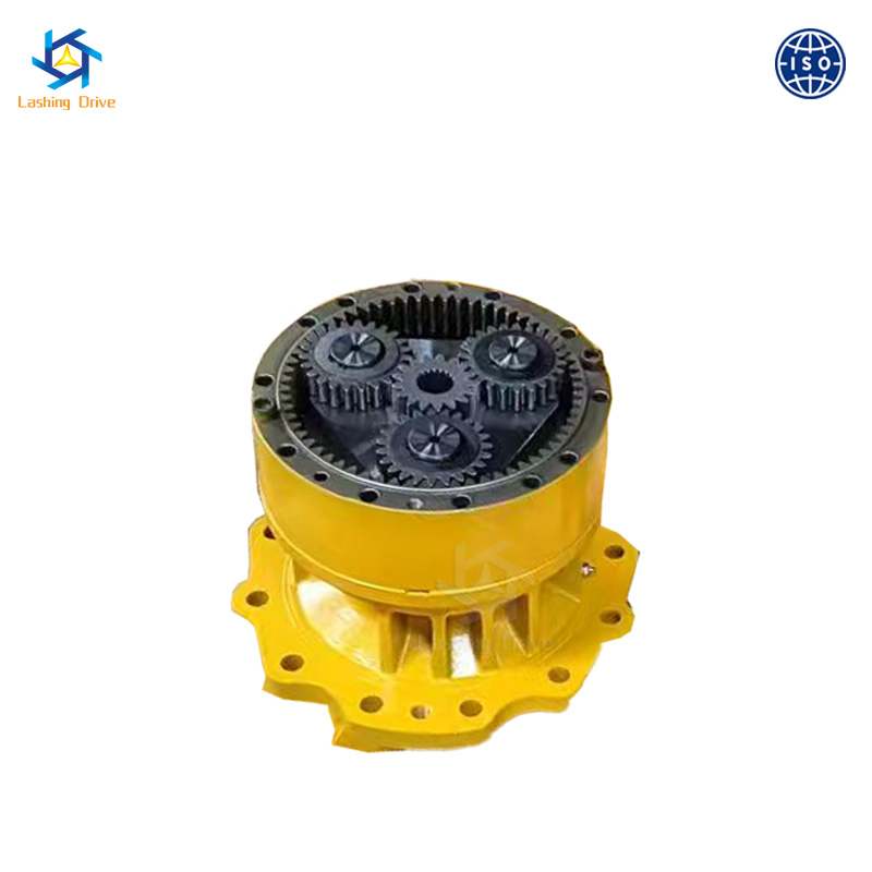
When designing power transmission for heavy industrial applications, engineers frequently discover that standard parallel shaft or worm gearboxes simply take up too much space. Even worse, they fail to handle sudden impact loads. A planetary system provides a highly engineered alternative. Its fundamental architecture consists of a central sun gear, multiple planet gears mounted on a rotating carrier, and a stationary outer ring gear.
The primary mechanical advantage of this intricate design is load distribution. In a traditional gearbox, power flows through a single point of contact between two gear teeth. This creates a highly concentrated stress point. In contrast, a planetary system distributes the input force across multiple planet gears at the exact same time.
Because the mechanical burden is shared among several gear meshes, the bending stress on individual gear teeth drops significantly. This inherent load-sharing capability allows the system to absorb severe shock loads. Imagine a rock crusher suddenly jamming. A planetary drive absorbs that violent impact and transfers substantially higher torque than conventional gearboxes of an equivalent physical size.
To truly understand the value, look at how planetary designs stack up against older technologies in the field.
Feature | Planetary Gear Reducer | Parallel Shaft Gearbox | Worm Gearbox |
|---|---|---|---|
Torque Density | Extremely High | Moderate | Low |
Shock Load Resistance | Excellent due to load sharing | Good | Poor |
Installation Footprint | Compact coaxial design | Large and bulky | Compact right-angle design |
Mechanical Efficiency | Up to 97 percent per stage | Up to 95 percent per stage | 50 to 85 percent |
Selecting the correct drive system is a rigorous process. It requires a holistic evaluation of the driven machine operating conditions. You cannot simply pluck a nominal torque value from a manufacturer catalog and hope for the best.
Torque is the rotational force required to drive your application. System designers must evaluate it in two distinct phases.
Determine Nominal Torque: This is the baseline force required to keep the machine running smoothly under normal steady-state conditions.
Calculate Peak Torque: This represents the absolute maximum force required during startup, rapid acceleration, or when encountering sudden material blockages.
The selected gear reducer must possess a nominal rating that comfortably exceeds the continuous operating torque. More importantly, its peak rating must withstand maximum intermittent shock loads without yielding the gear teeth or shearing the internal shafts.
The gear ratio determines exactly how the input speed from the prime mover is reduced. This inversely multiplies the output torque. For instance, a 100 to 1 ratio reduces a 1500 revolutions per minute input down to a 15 revolutions per minute output. This multiplies the torque proportionally, minus minor efficiency losses.
Input speed limitations must be strictly observed. Manufacturers specify maximum allowable input speeds based on bearing thermal limits and lubrication dynamics. Exceeding these rotational limits causes excessive internal friction. The oil degrades rapidly. Ultimately, the bearings suffer premature thermal failure.
The Service Factor acts as a critical safety multiplier applied to your baseline torque calculation. It accounts for the harsh realities of the operating environment, the daily duty cycle, and the unpredictable nature of the load.
A machine running 24 hours a day with heavy shock loads requires a much higher service factor than a lightly loaded conveyor running only a few hours a day. Applying the correct service factor ensures the gearbox possesses adequate mechanical reserves. This guarantees it achieves its intended design life under actual field conditions.
For severe-duty applications requiring immense power density, standard commercial gearboxes are entirely insufficient. In these brutal scenarios, heavy-duty industrial series are specified by procurement teams and lead engineers.
The p series planetary gear reducer is characterized by its robust, highly modular architecture. When you look at the technical specifications, the advantages become clear. Typical units offer a massive torque range from 22,000 Newton meters up to 2,600,000 Newton meters. The modularity allows engineers to stack multiple planetary stages, easily achieving ratios from 25 to 1 up to 4000 to 1.
Key design hallmarks include heavy-duty nodular cast iron housings. These housings resist torsion and aggressively dampen vibrations under heavy load. The internal components feature case-hardened and precision-ground alloy steel gears. This ensures maximum contact area and supreme wear resistance. Furthermore, these units come equipped with high-capacity tapered roller bearings designed specifically to absorb extreme radial and axial forces.
Due to their exceptional torque density, these units excel in the most demanding environments on earth. Imagine a bucket wheel excavator biting into solid rock. The drive system must absorb that violent impact without failing. Common applications include driving apron feeders and heavy-duty conveyors in mining. They power massive stacker-reclaimers in bulk material handling, operate rolling mill drives in steel plants, and drive large-scale high-viscosity agitators in chemical processing.
Electric motors dominate stationary factory floors. However, mobile equipment and specialized heavy machinery often rely entirely on fluid power. Integrating hydraulic systems with planetary gearing requires a specific set of sizing rules.
The synergy between fluid power and planetary gearing is incredibly effective. Hydraulic motors provide stepless variable speed control, dynamic braking capabilities, and exceptional starting torque right from zero speed. When coupled with a planetary gearbox, this input is multiplied into massive output torque. This setup is perfect for moving extreme loads at crawling speeds.
A hydraulic motor driven planetary reducer is the standard trusted solution. You will find them on track drives for excavators, heavy-duty winch drives on offshore cranes, and slew drives on deep-hole drilling rigs. These units often feature integrated multi-disc parking brakes with holding torques specifically calibrated to secure massive static loads.
Sizing a hydraulic-driven unit requires meticulously matching the hydraulic motor displacement in cubic centimeters per revolution and maximum operating pressure with the gearbox input mechanical limitations. Engineers must ensure that maximum hydraulic pressure spikes do not generate an input torque that exceeds the reducer structural limits during stall conditions.
During the sizing phase, the holding torque of the internal fail-safe brake must be verified. It must safely exceed the maximum static load of the application. This is absolutely critical in lifting operations or steep incline scenarios.
Even with flawless torque calculations, secondary environmental and thermal factors can cause a perfectly sized gearbox to fail prematurely. Addressing these challenges during the specification phase is non-negotiable.
A frequent and costly sizing error is focusing solely on the mechanical horsepower rating while completely ignoring the thermal rating. The mechanical rating dictates what the steel gears and shafts can physically withstand. In contrast, the thermal rating dictates the maximum continuous power the gearbox can transmit before the internal oil temperature exceeds safe limits, typically around 90 to 100 degrees Celsius.
In high-power continuous-duty applications, the mechanical capacity often far exceeds the thermal capacity. If the application pushes past the thermal limit, the oil film breaks down rapidly. This leads to destructive metal-to-metal contact. Engineers must mitigate this by specifying auxiliary cooling systems. Options include shaft-driven cooling fans, external oil-to-air heat exchangers, or internal water-cooling jackets.
Operating environments heavily influence final gearbox selection. Extreme ambient temperatures drastically affect oil viscosity. Sub-zero environments may require internal oil heaters to prevent pump cavitation during startup. Desert environments further reduce the unit thermal capacity.
Furthermore, applications in cement plants or aggregate quarries expose the reducer to highly abrasive dust. Standard lip seals will fail quickly here. Engineers must specify taconite seals, labyrinth sealing systems, or purgeable grease cavities to block particulate ingress and protect the vital internal bearings.
Precise engineering calculations establish the theoretical mechanical limits of a drive system. However, rigorous maintenance protocols dictate its actual operational lifespan. In high-torque environments subjected to heavy shock loads, bearing life and gear fatigue limits are directly tied to lubrication quality.
Lubrication at low rotational speeds presents a unique physical challenge. At crawling speeds, gear teeth may fail to generate a sufficient hydrodynamic fluid film to separate the mating metal surfaces. To counteract this boundary lubrication condition, selecting the correct oil viscosity is paramount.
Heavy-duty applications typically require high-viscosity synthetic gear oils fortified with Extreme Pressure additives. These additives chemically bond to the metal. They create a sacrificial protective layer that prevents galling under peak loads.
The delivery method must also align with the duty cycle. Splash lubrication is often sufficient for standard horizontal mounts. However, vertical orientations or continuous heavy-duty cycles often mandate a forced-circulation system. In these setups, an external pump continuously delivers filtered cooled oil directly into the mesh points of the p series planetary gear reducer.
Implementing a predictive maintenance strategy is far cheaper than reactive emergency repairs. Facility managers should adhere to a strict inspection hierarchy. Quarterly spectroscopic oil analysis is the most critical diagnostic tool. It detects microscopic wear metals long before failure occurs. Monthly vibration monitoring can identify misalignments or bearing defects early. Finally, routine thermal profiling and daily visual checks for seal leaks ensure the system remains within its safe operating window.
Precise sizing prevents catastrophic mechanical failures in heavy industrial equipment. By thoroughly understanding your load profiles, calculating both nominal and peak torque, and accounting for external forces, you ensure maximum reliability. Choosing the correct drive system guarantees long-term operational success and protects your capital investment.
Always match torque ratings and thermal capacities to your specific real-world applications to keep your production moving flawlessly. If you are engineering a new heavy-duty drive system or upgrading an existing line, partnering with a proven manufacturer is your best defense against downtime. Evaluate your specific torque requirements and explore specialized industrial solutions at https://www.cnlashing.com to find the exact planetary gear reducer engineered for your toughest applications.
The maximum torque capacity varies significantly based on the physical size, the number of planetary stages, and the specific engineering series. While smaller precision-oriented units might handle a few hundred Newton meters, heavy-duty industrial variants are engineered for massive force multiplication. These robust industrial reducers can comfortably manage torque outputs ranging from 25,000 up to well over 2,600,000 Newton meters. The absolute maximum limit is dictated by the shear strength of the gear teeth, the load-bearing capacity of the output shaft, and the structural rigidity of the carrier and housing.
Calculating the required gear ratio is a fundamental step in matching the prime mover to the driven load. The basic formula is straightforward. Gear Ratio equals Input Speed divided by Desired Output Speed. For example, if your electric motor runs at 1450 revolutions per minute and your application requires the driven shaft to rotate at 14.5 revolutions per minute, the required gear ratio is 100 to 1. In planetary systems, high ratios are achieved by stacking multiple gear stages sequentially.
Hydraulic motor driven systems are selected over electric drives primarily for their exceptional power density and operational versatility in harsh environments. Hydraulic setups deliver maximum torque immediately from zero speed. This is critical for applications like heavy winches, tunnel boring machines, and mobile track drives. Furthermore, hydraulic systems are inherently safer in explosive or highly flammable environments because they eliminate the risk of electrical sparking.
The P series is specifically architected for the most demanding high-torque industrial environments. It differentiates itself through several key engineering upgrades. First, it utilizes a highly rigid heavy-duty nodular cast iron housing designed to prevent deflection under extreme radial and axial loads. Second, the internal metallurgy features premium case-hardened alloy steels with optimized gear tooth geometry. Additionally, it employs a modular design philosophy, allowing engineers to easily configure various input adapters and output shafts.
Undersizing a gear reducer inevitably leads to catastrophic mechanical failure and costly unplanned operational downtime. When a gearbox is subjected to loads exceeding its mechanical rating, the gear teeth experience excessive bending stress. This leads to root fatigue and eventual tooth breakage. The mating surfaces will suffer from macropitting and scoring due to the breakdown of the lubrication film. Furthermore, undersized bearings will rapidly degrade, causing shaft deflection and ultimate system seizure.
Ambient temperature directly impacts the thermal capacity and lubrication efficiency of the gearbox. In high heat environments, the oil thins out, losing its protective film thickness, and the gearbox struggles to dissipate internal heat. This often requires engineers to upsize the gearbox to increase thermal mass or add external oil coolers. Conversely, extreme cold thickens the oil, which can cause internal pumps to cavitate during startup, necessitating built-in oil heaters.
When properly sized with the correct service factor and maintained with strict lubrication protocols, a heavy-duty planetary gearbox is designed to last anywhere from 10,000 to over 50,000 operational hours. The actual lifespan heavily depends on the severity of shock loads, the cleanliness of the operating environment, and strict adherence to routine oil analysis and replacement schedules.