Views: 0 Author: Site Editor Publish Time: 2026-09-10 Origin: Site
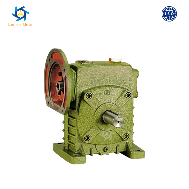
Specifying an industrial right-angle drive requires exact alignment between required output torque, mechanical footprint, and motor compatibility. Engineers often face strict spatial limitations when designing equipment layouts. They must balance heavy load requirements against increasingly tight installation spaces. You need robust power transmission components to keep operations running smoothly. We introduce the WP series drive as an industry-standard power transmission solution. Its central specification directly governs both mechanical capacity and physical envelope. This critical metric is the center distance.
Our purpose is to provide a technical evaluation framework for selecting the correct center distance and frame size. You will learn to evaluate mechanical constraints accurately. We explore methods to prevent thermal overload in demanding applications. We also guide you through avoiding mounting incompatibility during system retrofits. Understanding these engineering fundamentals ensures your automated systems maintain peak performance under stress.
Center distance is the primary metric dictating a WP worm reducer's torque capacity and thermal rating.
Selecting the correct wp worm gearbox frame size ensures alignment with input motor standards (NEMA/IEC) and physical mounting constraints.
Undersizing for the sake of utilizing a compact worm reducer can lead to thermal bottlenecking; physical footprint must be balanced with service factor requirements.
Accurate cross-referencing of center distances is critical when replacing legacy right-angle solid shaft gearboxes to ensure drop-in bolt pattern compatibility.
Engineers define center distance as the exact measurement between the center axis of the input worm shaft and the center axis of the output worm wheel. This single dimension dictates the internal geometry of the gearset. A larger distance allows for larger gear teeth. Larger gear teeth create a significantly wider surface contact area during mesh. This contact area directly influences how much torque the geartrain can transmit safely. By establishing the wp worm reducer center distance, you set the baseline mechanical capability of the entire drive unit.
Increasing the center distance exponentially increases permissible output torque. A small bump in physical size yields a massive jump in load-carrying capacity. The mechanical strength of the bronze gear relies on its pitch diameter. A larger pitch diameter provides higher leverage against the output shaft. You cannot linearly scale expectations. Moving from a 50mm to a 100mm center distance often triples the output torque limit. Engineers must consult performance tables to verify these non-linear jumps. Overlooking this exponential relationship leads to severe undersizing or wasteful oversizing.
Center Distance (mm) | Relative Torque Capacity | Housing Volume Expansion | Typical Application Scale |
|---|---|---|---|
40 - 60 | Low (Baseline) | Minimal | Light Conveyors, Packaging |
70 - 100 | Moderate (2x - 3x Baseline) | Moderate | Material Handling, Agitators |
120 - 150 | High (4x - 6x Baseline) | Large (High Oil Capacity) | Heavy Automation, Elevators |
175 - 250 | Extreme (8x+ Baseline) | Massive (Maximum Dissipation) | Mining, Heavy Industrial Milling |
Center distance directly dictates the volume of the cast housing. Housing volume determines the unit's oil capacity and exterior surface area. These physical dimensions set the absolute thermal dissipation limits of any WP worm reducer. Mechanical gears generate heat continuously under load. The lubricating oil absorbs this heat. The housing then transfers the heat into the surrounding air. A smaller housing holds less oil and features less surface area. Consequently, smaller units overheat rapidly under continuous heavy loads. You must evaluate thermal ratings alongside mechanical torque limits.
Center distance establishes baseline load limits. However, inherent gear sliding friction changes the engineering approach. Worm gears slide against each other rather than rolling smoothly. This sliding action generates substantial friction and heat. Larger center distances handle higher mechanical loads but also generate more total heat at high speeds. You must account for thermal service factors. Standard industry practices recommend adjusting service factors based on duty cycle. Continuous operation demands a higher thermal service factor than intermittent operation. Relying solely on mechanical strength leads to early lubricant breakdown.
Manufacturers categorize these industrial reducers using specific numerical designations. Common sizes range from 40 to 250. This number typically reflects the exact center distance in millimeters. A size 80 unit features an 80mm distance between the shafts. This naming convention simplifies initial engineering calculations. You immediately know the physical scale of the unit. However, you must verify the specific suffix codes. Suffix letters often denote housing orientation, input shaft style, or mounting flange type. Standardized naming helps you cross-reference different manufacturer catalogs quickly.
Matching the gearbox to your drive motor requires precise evaluation. You must align the wp worm gearbox frame size with standard motor input flanges. American engineers frequently use NEMA standard frames, such as 56C or 145TC. European systems rely on IEC metric frames, like 71B5 or 80B14. The input flange diameter and bore size must match the motor shaft exactly. An incompatible flange forces you to use custom adapter plates. Adapter plates add unnecessary length and introduce potential alignment errors. Always confirm input bore dimensions before finalizing your equipment specification.
Right-angle solid shaft outputs remain the standard for heavy-duty applications. Solid shafts handle high overhung loads and heavy shock impacts exceptionally well. They integrate easily with chain sprockets and belt pulleys. Conversely, hollow bore designs slide directly onto the driven machine shaft. Hollow bores eliminate the need for external couplings. This direct mounting saves significant lateral space. However, hollow bore designs require strict shaft tolerances. You must also secure them using torque arms to prevent the entire housing from spinning. Choose your output style based on load type and available mounting space.
Standard frame sizes sometimes fall short of extreme application demands. A single-stage gearset typically caps out around a 60:1 or 80:1 ratio. Pushing a single stage higher drastically reduces efficiency. When you require ratios like 300:1 or 900:1, you need multi-stage solutions. Double-speed reducers stack a primary unit onto a secondary unit. This combination multiplies the ratio without demanding a massive primary center distance. Multi-stage setups keep the overall footprint manageable. They deliver incredibly slow, high-torque output speeds ideal for heavy positioning tasks.
Modern automated machinery demands maximum performance in minimum space. Conveyor systems and packaging machines leave very little room for bulky drive components. Engineers face a tough trade-off. Specifying a compact worm reducer solves the spatial footprint problem immediately. However, compact units have lower oil capacities. They heat up much faster under continuous duty. You must balance the physical envelope against the required service factor. Sometimes, you must upgrade the lubricant to full synthetic oil to survive the thermal bottleneck of a small footprint.
Standard industrial units feature heavy cast iron housings. Cast iron provides incredible durability. It naturally dampens vibrations and resists sudden shock loads. Unfortunately, cast iron is heavy and bulky. Aluminum alternatives offer massive weight savings. Aluminum also dissipates heat faster than cast iron. This rapid heat transfer makes aluminum ideal for compact applications. However, aluminum housings cannot withstand heavy impacts. They perform best in smooth, uniform load environments. You must match the housing material to the physical environment and load profile.
Specific environments dictate stricter material requirements. Food processing plants and pharmaceutical facilities require washdown-capable equipment. Harsh cleaning chemicals destroy standard cast iron and aluminum finishes quickly. In these scenarios, you must specify stainless steel variants. Stainless steel resists corrosion perfectly. However, stainless steel retains internal heat much longer than aluminum. This poor thermal conductivity limits the availability of ultra-compact stainless models. You generally have to specify a larger center distance just to manage internal temperatures. Always consider thermal dynamics when selecting specialized housing materials.
Industrial components eventually fail under continuous stress. When a legacy right-angle drive breaks, production stops. You need a fast, drop-in replacement. Modifying the machine baseplate takes too much time. You must measure the existing failing unit precisely. Start by locating the original manufacturer nameplate. If the nameplate is illegible, grab your calipers. You must reverse-engineer the physical dimensions. A successful replacement requires identifying the exact center distance first. This single measurement narrows down the available replacement options instantly.
Matching the center distance is only the first step. You must validate several other critical physical dimensions.
Shaft Height: Measure from the base feet to the center of the output shaft. A mismatch here requires shimming or milling.
Bolt Hole Pattern: Verify the distance between mounting holes on the base. Incorrect patterns require drilling new holes in the machine frame.
Output Shaft Diameter: Measure the solid shaft diameter and keyway width. Mismatched shafts will not fit your existing sprockets or couplings.
Input Flange: Ensure the new unit accepts your existing electric motor safely.
Engineers rely on comprehensive cross-reference charts to switch brands smoothly. Major brands like Dodge publish conversion guides. You use these guides to match physical footprints. However, you must look beyond the physical size. A size 70 unit from Brand A might have a different thermal rating than a size 70 from Brand B. You must verify application service factors. Review the gear material specifications and bearing ratings. Ensure the replacement WP series matches the legacy unit’s mechanical endurance. Never sacrifice service factor merely to achieve a quick physical fit.
Define the required continuous output torque based on the driven load.
Determine the operating hours per day (e.g., 8 hours vs. 24 hours).
Identify the shock load classification (uniform, moderate shock, or heavy shock).
Establish the minimum acceptable service factor using standard AGMA guidelines based on these variables.
Calculate the exact target ratio by dividing input motor speed by desired output speed.
Take the required torque and multiply it by your calculated service factor.
Consult manufacturer performance tables using this adjusted torque value.
Select the baseline center distance that safely handles the adjusted torque at your specific ratio.
Check the physical dimensions of the selected frame size against your machinery layout.
Confirm clearance around the housing for proper ventilation and future oil changes.
Verify the input flange dimensions exactly match your selected NEMA or IEC motor standard.
Ensure the motor shaft length does not bottom out inside the input bore.
Select the necessary output shaft style: single solid, dual solid, or hollow bore.
Determine the mounting orientation: standard foot-mounted, flange-mounted, or universal.
Confirm the breather plug placement aligns with the final mounting position to prevent oil leaks.
Verify the overhung load capacity of the output shaft if using belts or chains.
Successful WP series drive selection requires a strict engineering balance. You must weigh heavy mechanical demands against unforgiving spatial realities. Finalizing the center measurement first guarantees your physical frame choice survives long-term thermal stresses. Avoid undersizing units simply to fit a tight footprint, as thermal breakdown happens rapidly under continuous loads. Take time to measure legacy units precisely during retrofits to ensure drop-in compatibility. Always consult detailed manufacturer datasheets, dimensional drawings, or an application engineer before finalizing procurement to avoid installation errors.
A: You measure it by finding the exact perpendicular distance between the center axis of the high-speed input worm shaft and the center axis of the low-speed output gear shaft. This dimension is typically expressed in millimeters and defines the unit's core frame size category.
A: Yes, intermittent duty cycles generate less total heat. A lower duty cycle allows for a reduced thermal service factor. You can often safely select a smaller unit for intermittent tasks, provided the mechanical torque limit still exceeds your system's peak starting loads.
A: Single-stage units typically offer ratios ranging from 10:1 up to 60:1, though some reach 80:1. Pushing beyond 60:1 in a single stage significantly drops mechanical efficiency. For ratios higher than this range, engineers recommend multi-stage (double reduction) assemblies.
A: You must verify the reducer's input flange specifications match your motor's standard NEMA (e.g., 56C) or IEC (e.g., 71B5) designation. Strictly confirm the input bore diameter, keyway width, and pilot flange diameter to guarantee a precise, vibration-free physical connection.