Views: 0 Author: Site Editor Publish Time: 2026-09-01 Origin: Site
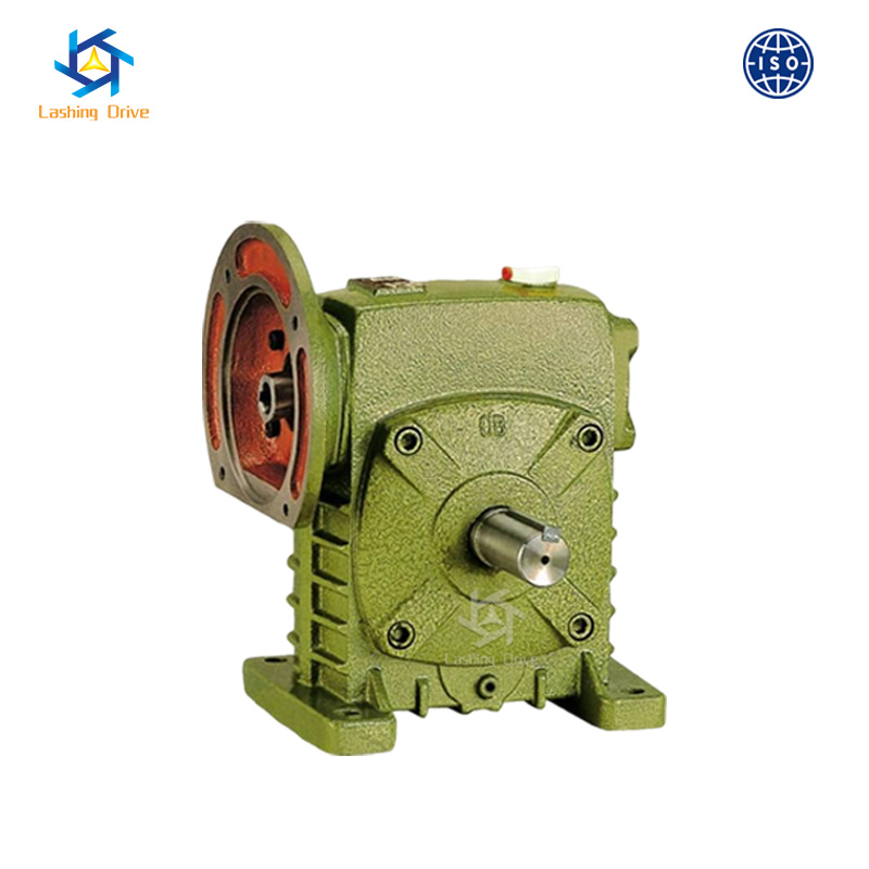
Engineers constantly balance mechanical risk and operational efficiency when specifying industrial gearboxes for modern manufacturing facilities. Undersizing a unit leads to catastrophic bronze gear wear, sudden mechanical failure, and completely unexpected factory downtime. Conversely, oversizing unnecessarily inflates project budgets, complicates mounting logistics, and requires a significantly larger physical footprint on the plant floor. The standard WP series cast-iron reducers—which include the widely used WPA, WPS, WPO, and WPX models—serve as the dependable workhorses for thousands of conveyors, industrial mixers, and heavy agricultural machinery worldwide. However, understanding exactly how much mechanical force they can safely transmit remains crucial for sound system design. This comprehensive guide outlines how to accurately calculate, critically evaluate, and precisely verify the usable output torque of a WP worm reducer. You will learn the core mechanical variables dictating gearbox performance and discover specific sizing criteria for various frame sizes. We will also explore thermal limitations, service factor applications, and structural upgrades to ensure optimal long-term reliability.
Output torque in WP series reducers is dictated by center distance (frame size), input speed, and reduction ratio.
Usable mechanical torque is often lower than theoretical maximums due to thermal horsepower limitations.
High gear ratios offer a self-locking worm gearbox capability, but at the cost of significant efficiency losses.
Applications with extreme shock loads or continuous heavy duties may require stepping up to a double-enveloping worm gear reducer rather than a standard cylindrical WP model.
Understanding torque delivery requires a close look at mechanical physics and gear geometry. We calculate output torque (measured in Newton-meters or Nm) by evaluating the motor's input power, the exact gear reduction ratio, and the inherent mechanical efficiency of the unit. The standard formula multiplies the input power by the gear ratio, adjusts downward for internal efficiency losses, and divides the result by the output speed. Engineers must recognize how internal friction directly dictates these outcomes. You can never assume flawless power transmission. The sliding friction between the steel worm shaft and the bronze worm wheel inherently dissipates valuable mechanical power as heat.
The center distance serves as the primary benchmark for overall torque capacity. We define this vital metric as the exact physical distance between the center axis of the worm shaft and the center axis of the worm wheel. Standard models feature center distances ranging from a compact 40mm up to a massive 250mm. This physical dimension strictly dictates the maximum allowable gear stress. A larger center distance accommodates significantly larger gear teeth. Bigger, thicker teeth naturally resist severe shear forces much better during heavy industrial operation.
Furthermore, input speed dramatically influences the final torque capacity. The rotational RPM of the driving motor directly changes how much mechanical force the gearbox safely transmits. A standard electric motor spinning at 1400 RPM yields entirely different torque limits than an older motor operating at 900 RPM. Lower input speeds often allow for slightly higher output torque ratings. The internal gear mesh experiences far less dynamic impact and heat generation at reduced rotational speeds. We strongly advise engineers to review manufacturer performance curves for precise RPM correlations before finalizing designs.
Selecting the right frame size requires mapping your specific mechanical load demands to standardized catalog specifications. Manufacturers generally categorize these robust units by their center distance measurements. We see three distinct performance tiers in the broader industrial landscape.
Small frames encompass the WP 40 through WP 80 designations. These compact units typically output strictly limited mechanical force, usually spanning between 15 Nm and 150 Nm of torque. They fit perfectly into low-load factory automation systems. You will often spot these smaller frames driving light packaging machines, miniature assembly line conveyors, and simple rotary indexing tables. Their compact cast-iron bodies successfully resist external environmental damage while saving critical floor space.
Medium frames span the middle territory, encompassing WP 100 to WP 135 models. Expected torque output limits here increase substantially, ranging roughly from 200 Nm to 500 Nm. This specific category accurately represents the most common industrial use cases globally. Production facilities rely heavily on them for medium-duty liquid mixers, standard material handling belts, and agricultural feed systems. They offer mechanical engineers a highly practical balance of manageable physical size and respectable mechanical output.
Large heavy-duty frames include massive models like the WP 155, WP 175, WP 200, and WP 250. Structuring a true high-torque wp worm reducer setup absolutely requires these heavy iron casings. Torque ranges here easily push from 1,000 Nm to well over 3,000 Nm. Systems engineers specify these formidable sizes for highly aggressive, unyielding applications. Think of mining material hoists, heavy aggregate conveyors, and large-scale chemical agitation tanks requiring immense startup force.
Frame Category | Common Models | Approximate Torque Range (Nm) | Ideal Industrial Applications |
|---|---|---|---|
Small | WP 40, WP 50, WP 60, WP 80 | 15 - 150 | Light packaging, miniature assembly conveyors, low-load automation |
Medium | WP 100, WP 120, WP 135 | 200 - 500 | Medium-duty liquid mixers, standard material handling belts |
Large (Heavy-Duty) | WP 155, WP 175, WP 200, WP 250 | 1,000 - 3,000+ | Mining material hoists, aggregate conveyors, chemical agitation |
Engineers frequently choose these specific gearboxes for their unique mechanical traits extending far beyond simple speed reduction. Load holding represents a major operational advantage in vertical lifting systems. Certain internal configurations inherently resist back-driving during sudden electrical power loss.
We define the primary self-locking threshold by analyzing both the gear ratio and the lead angle of the worm thread. Ratios stepping above 40:1 or 50:1 generally provide reliable static self-locking behavior. In these high-ratio setups, the worm thread lead angle drops below three degrees. Consequently, the resting load cannot physically force the output shaft to rotate backward against the stationary electric motor. This geometric trait provides a natural, highly effective self-locking worm gearbox capability for incline conveyors and standard lifting hoists.
However, maximizing your torque multiplication through these high ratios creates an unavoidable efficiency tradeoff. High-ratio gear sets suffer from immense internal sliding friction. Standard gearbox efficiency can frequently plummet below 50 percent in these extreme scenarios. You must proactively supply significantly more initial motor power simply to overcome this internal heat and drag.
We must also sternly warn against relying entirely on self-locking features for critical safety. Industrial environments experiencing high ambient vibration pose significant risks to this mechanism. Severe mechanical vibration can temporarily break the static friction holding the gears tightly together. This physical phenomenon causes theoretically locked gearboxes to slowly creep downward over time. We always recommend installing external braking systems for critical safety loads involving human operators.
Standard cast-iron models handle typical operational tasks beautifully, but extreme industrial applications inevitably demand specialized engineering solutions. You will eventually hit firm structural limits where a standard cylindrical gearset design falls dangerously short of system requirements.
Contact area differences clearly dictate these mechanical limitations. A standard WP unit utilizes a traditional cylindrical worm. This specific geometry typically engages only one or two bronze gear teeth simultaneously. Therefore, all transmitted rotational force focuses entirely on a dangerously tiny surface area during operation. Conversely, multi-tooth engagement perfectly defines double-enveloping designs. Often known as cone drives, the worm elegantly wraps around the circular curvature of the mating gear. This specialized geometry securely engages up to eight teeth at once.
This fundamental geometric shift fundamentally alters the internal torque density of the system. By spreading the brutal operating load across multiple teeth simultaneously, a double-enveloping worm gear reducer handles massive force without fracturing. It can easily deliver up to two or three times the torque capacity within the exact same physical footprint. You gain massive power upgrades without rebuilding your existing mounting infrastructure.
Navigating the final decision framework requires objectively evaluating your space constraints and structural stress limits. Simply sizing up to a larger standard WP frame remains the easiest path if physical space permits. A larger standard cast-iron frame usually demands less capital upfront. However, if your machine design strictly restricts physical space, or if the environment involves aggressive shock loads, the advanced multi-tooth upgrade becomes mathematically necessary.
Catalog specifications routinely present theoretical maximums calculated under flawless laboratory conditions. Real-world implementation on a dusty factory floor looks very different. We must clearly differentiate between what a gearset survives mechanically and what it actually survives thermally.
Continuous operation constantly generates significant friction and damaging heat. A specific unit might easily handle 500 Nm mechanically without snapping a single bronze tooth. However, it will rapidly fail thermally if run continuously without adequate ambient cooling. Internal lubrication oil degrades rapidly when operating temperatures exceed safe limits. We call this firm barrier the thermal horsepower limit. You must rigorously verify that your continuous application does not outpace the iron casing's ability to shed heat.
Engineers universally use specific service factors (fs) to logically bridge the gap between theoretical ratings and actual factory demands. You adjust the baseline required torque upward based on specific application variables. Consider these crucial adjustments:
Total operation hours: Running a heavy machine 24 hours a day demands a significantly higher safety multiplier than a simple four-hour daily shift.
Expected load types: Uniform, smooth loads require far less safety margin than moderate or severe shock loads found in rock crushing equipment.
Cyclic start rates: Frequent, aggressive starts and stops per hour generate massive stress spikes throughout the entire drive train.
Overhung load (OHL) strictly limits real-world capability. We define overhung load as external radial forces acting aggressively on the extended output shaft. Attaching heavy chain sprockets, steel gears, or wide tension pulleys directly to the shaft pulls it violently sideways. This radial stress heavily strains the internal support bearings. High radial forces lower the actual usable torque the internal components can safely transmit without deflection.
Buying robust industrial gearboxes requires strict attention to minute mechanical details. A single missing variable during the early procurement phase often leads to premature field failure. We strongly recommend following a highly structured evaluation process.
Comprehensive Application Review: You must diligently collect precise operational data before contacting any suppliers. Determine the exact motor power driving the current system. Calculate your rigidly required output RPM based on precise process needs. Document the peak ambient temperature of your operating facility. Finally, clearly define the intended duty cycle to establish highly realistic thermal limits.
Accurate Mounting Orientation: The broad WP family includes multiple physical configurations to seamlessly match spatial needs. You must consciously choose between bottom-shaft (WPA), top-shaft (WPS), or specific vertical orientations (WPX). Specifying the absolutely correct model matters immensely for internal lubrication pooling. An incorrectly mounted unit rapidly starves upper bearings of vital oil. This immediately triggers dry-start torque failures and catastrophic bronze wear.
Strict Vendor Validation: Establish rigorous evaluation criteria for the manufacturer. Look closely at their stated machining tolerances. Ask the engineering team directly about their specific bronze alloy quality. Poorly cast bronze wheels inevitably shear under heavy operational loads. Check the overall casing rigidity to ensure the heavy cast iron physically resists twisting under load. Reputable manufacturers gladly provide verifiable testing data regarding their metal strength.
Accurately specifying mechanical torque requires significantly more effort than reading a single static number on a marketing specification sheet. Design engineers must carefully balance physical frame size limits, optimal gear reduction ratios, and highly critical thermal thresholds. Identifying the precisely correct mechanical geometry ensures seamless, uninterrupted power transmission across your facility. Failing to properly account for heat dissipation limits or excessive overhung loads will rapidly compromise even the strongest cast-iron housings.
Before finalizing any major equipment purchase, industrial buyers should rigorously calculate their rigidly required service factor. Honestly evaluate your specific daily operational hours and real-world shock load risks. We highly encourage gathering your highly detailed load data and cyclic duty metrics. Reach out directly to an experienced engineering team with this critical information. Request highly accurate CAD models and professional mathematical sizing verification to guarantee your newly installed system performs flawlessly under immense pressure.
A: A standard WPA 200 typically handles between 1,500 Nm and 2,500 Nm of torque. The exact maximum depends heavily on the specific gear ratio and the motor's input speed. While it sits firmly in the heavy-duty spectrum, you must review your unique application context. Continuous duty cycles or heavy shock loads will require applying a service factor, effectively lowering the usable maximum rating.
A: This happens because mechanical ratings and thermal ratings differ significantly. The mechanical rating dictates gear strength before physical breakage. The thermal rating limits how much heat the casing can dissipate. Continuous operation generates immense sliding friction. If you run the gearbox constantly without cooling, the internal oil overheats long before you hit the mechanical breaking point.
A: No, attaching a larger motor is dangerous. Every center distance frame size possesses a strict mechanical limit. Forcing more horsepower into the gearbox than it was designed for will severely overload the internal components. You risk catastrophically shearing the bronze worm wheel teeth or twisting the input shaft under the excessive force.
A: No. High ratios (above 40:1) generally provide static self-locking, meaning they securely hold loads when completely stopped. However, dynamic self-locking differs greatly. If the machine operates in a high-vibration environment, the aggressive shaking can break the static friction. This causes the supposedly locked gearbox to creep backward over time. Always use external brakes for critical safety applications.